It is estimated that many people do not know what an omnipotent watch is. Actually, it is widely used in our lives. Because whether it is an engineer, an electrician, a beginner, an old electrician, or an ordinary resident, a universal meter is an electric tool that can be used as an electric field. , But do you really use a multimeter? Today, let Xiao Bian for everyone to briefly introduce the use of universal table and precautions.
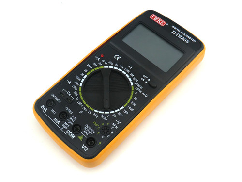
How to use the universal meter
First, the voltage measurement
1, DC voltage measurement, like batteries, walkman power and so on. The steps are: insert the black meter pen into the hole labeled "com" and the red meter pen into the hole labeled "V Ω". Then turn the knob to a larger range than the estimated value (note: the values ​​on the dial are the maximum range, "V-" for the DC voltage, "V ~" for the AC voltage, "A" for the current), then Connect the test leads to the power supply or battery terminals to maintain contact stability. At this point, the value can be read directly from the display. If “1.†is displayed, it means that the range is too small. It will take a long time to measure; if “-†appears to the left of the value, the polarity of the The actual polarity of the power supply is opposite, and the red lead is connected to the negative pole.
2, AC voltage measurement. The steps are: insert the black meter pen into the hole labeled "com" and the red meter pen into the hole labeled "V Ω". Then turn the knob to the desired range at the “V~†AC position. Since the AC voltage is not positive or negative, the measurement method is the same as above. (No matter what kind of voltage, should pay attention to personal safety, do not touch the metal part of the test pen by hand.)
Second, the current measurement
1, DC current measurement. The procedure is: Insert the black meter pen into the hole marked “COMâ€. If it is measuring current greater than 200mA, then insert the red meter pen into the “10A†jack and turn the knob to the DC “10A†position; if the measurement is less than 200mA For the current, you need to insert the red meter pen into the “200mA†jack and turn the knob to the proper range within 200mA of DC. After all adjustments are made, you can start measuring. Note: When the multimeter is in series, it should be stable, so that you can read it. If “1.†is displayed, then a large amount of time will be added. If “-†appears on the left of the value, the current will flow from the black meter. multimeter.
2, AC current measurement. The steps are basically the same, but the gear should be turned to the AC gear. After the current measurement is complete, the red pen should be inserted back into the “VΩ†hole. If you forget this step and measure the voltage directly, you should be careful with your watch or The power supply will be scrapped in the "a green smoke rushes to the sky."
Third, the resistance measurement
The steps are: insert the test leads into the holes marked “COM†and “VΩ†respectively, then turn the knob to the required range in “Ωâ€, and then connect the test leads to the metal parts at both ends of the resistor. Resistance, but do not touch both ends of the resistor at the same time, otherwise it will affect the accuracy of the measured value, because the human body is a conductor of limited resistance. In addition, keep a good contact between the test leads and the resistors when reading. Note: The unit is "Ω" in the "200" position, "KΩ" in the "2K" to "200K" position, and "MΩ" in the "2M" position.
Fourth, the diode measurement
The digital multimeter can measure light emitting diodes, rectifier diodes, etc. The steps are: insert the black meter pen into the hole marked “com†and the red meter pen into the hole marked “V Ω â€. Then turn the knob to the "-|>||--" (do not draw this logo) file; connect the positive electrode of the diode with a red meter pen and the negative electrode of the black meter, which will show the forward voltage drop of the diode. The voltage drop of the Schottky diode is about 0.2V, the common silicon rectifier (1N4000, 1N5400 series, etc.) is about 0.7V, and the light emitting diode is about 1.8-2.3V. To change the test leads, the display shows “1â€, because the reverse resistance of the diode is large, otherwise the tube will be broken down. For the analog multimeter, the red meter pen is connected to the negative pole of the battery, and the black meter is connected to the positive pole of the battery. Therefore, if the impedance is small when using an analog meter diode, the black pen is positive at one end; if the resistance is large, the red One end of the test pen is negative. For the digital multimeter, if the resistance is small, the red pen is positive; the resistance is large, and the black pen is positive.

V. Triode measurement
The steps are: insert the black pen into the hole marked “comâ€, and insert the red pen into the hole marked “V Ω â€. The principle is the same as that of the diode. Assuming that the A pin is the base, connect the black pen to the pin. The red pen and the other two legs are in contact with the other two legs respectively; if both readings are about 0.7V, then the red pen is used to connect the A pin, and the black pen is touching the other two legs. If both display "1", the A leg is Base, otherwise it needs to be measured again, and this tube is a PNP tube. Then how to determine the collector and emitter? The digital meter can't use the pointer swing to judge it like the pointer table, then how can we do it? We can use the “hFE†file to judge: first set the stall to “hFE†file, You can see a row of small jacks next to the gear, divided into PNP and NPN tube measurements. The tube type has already been determined in the foregoing. The base is inserted into the corresponding tube type “b†hole, and the other two feet are respectively inserted into the “c†and “e†holes. At this time, the value can be read, that is, the β value; then the base is fixed; The two feet are aligned; comparing two readings, the positions of the pins with larger readings correspond to the surfaces “c†and “eâ€. Tips: The method can only be directly measured on small tubes such as the 9000 series. If you want to measure large tubes, you can use the wiring method, that is, using a small wire to lead three pins, it will be convenient.
Six, MOS FET measurement
N-channel is divided into domestic and Nissan, such as the former 3D01, 4D01, the latter's 3SK series. If you want to determine the G-pole (gate), you can use the polar table of the omnipotentiometer. If the positive and negative voltage drop between one leg and the other leg is greater than 2V, you will see “1†and this leg is the gate G. Then exchange the pens to measure the other two legs. When the pressure drop is small, the black pen is connected to the D pole (drain), and the red pen is connected to the S pole (source).
Multimeter use matters needing attention
1. Before starting, zeroing should be done so that the needle is at zero voltage or current.
2. During use, the hand can not touch the metal part of the pen, not only can ensure the accuracy of the value, but also can guarantee personal safety.
3, when measuring the power, can not shift, especially when the high voltage or high current, otherwise it will damage the table. If you need to change gears, you should disconnect the test leads before changing gears.
4. When using, universal meter must be placed horizontally to avoid error. At the same time, attention should also be paid to the disturbance of the external magnetic field.
5, after the measurement is completed, the switch should be placed in the maximum block of the AC voltage. If it is not used for a long period of time, it should also be taken out of its internal batteries to prevent the battery from corroding other devices in the watch.
Universal table maintenance
1. Do not connect more than 1000V DC voltage or more than 700V AC rms voltage.
2. When the function switch is in Ω position, the voltage source cannot be connected.
3, when the battery is not installed or not tightened, this table can not be used.
4, the test table pen removed and cut off the power before the battery or fuse.

Summary: The above is Xiaobian made today for everyone to use universal table related knowledge, I believe that my friends also have a certain understanding, the use of universal table and precautions, etc. Introduction we can refer to, I hope this The article is helpful to you.
The folding pole for streetlights is a new and innovative solution for urban lighting. It is designed to provide a convenient and practical way to install and maintain streetlights in tight spaces. The folding pole is made of high-quality materials and is engineered to withstand harsh weather conditions and heavy use.
The pole can be easily folded and stored when not in use, making it an ideal solution for temporary lighting applications. It can also be used in areas where traditional poles are not feasible due to space constraints or other limitations.
The folding pole is easy to install and can be quickly set up by a single person. It can be adjusted to different heights and angles, allowing for customized lighting solutions that meet the specific needs of any project.
Overall, the folding pole for streetlights is a versatile and practical solution that offers a range of benefits to urban planners, lighting designers, and maintenance crews.
Street Light Flexible Pole,Outdoor Light Pole,Steel Pole,Adjustable Pole,Hinged Pole,Octagon Pole
Yangzhou M.T. New Energy & Lighting Group Co., Ltd. , https://www.mtstreetlight.com