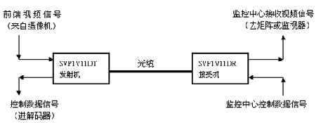
First understand the basic structure of the optical transceiver. Take the one-way video and one-way reverse data that are commonly used in engineering as an example.

The transmission method of video is: the video signal from the front-end camera enters the VIDEO IN interface of the optical transmitter (SVP1V11DT), and the electrical signal is converted into an optical signal. The optical signal is transmitted to the optical receiver (SVP1V11DR) of the monitoring and command center through the optical cable. The optical receiver restores the optical signal into a video signal and enters a monitor or a monitoring matrix.
The transmission path of control data is: the control data signal sent from the command center enters the optical transceiver from the data inlet DATE IN of the optical receiver (SVP1V11DR), the electrical signal is converted into an optical signal, and the optical signal is transmitted to the front-end optical transceiver (SVP1V11DT) through the optical cable. After photoelectric conversion, the control code is restored and output to the decoding box through the data interface to control the actions of the front-end PTZ and camera.
Note: Generally, the transmission direction of the video signal is the forward direction, and the data / audio signal opposite to the video signal transmission direction is called reverse data / audio. Data / audio with the same transmission direction as the video signal is called co-directional data / audio. The optical transmitter of a video signal is defined as a transmitter, and the optical receiver of a video signal is defined as a receiver.
Optical transceiver selection index
1. Type of optical transceiver: analog optical transceiver / digital optical transceiver single-mode / multi-mode
2. Transmission distance: optical cable length / optical cable link loss (very important)
3. Video:
Video channels: 1 channel / 2 channels / 4 channels / 8 channels / 16 channels / 32 channels / 48 channels Connection method: direct connection / video splitter / picture splitter / character superposition / other display methods: monitor / large Screen / TV / Other
4. Data:
Number of data channels: 1 channel / 2 channels / 3 channels / 4 channels Data type: RS232 / RS485 / RS422 / TTL / other Data direction: reverse / codirectional / bidirectional Rate (bps): 2400/4800/9600
Data use: control / alarm / cascade / picture / transportation facilities
5. Audio:
Number of audio channels: 1 channel / 2 channels / 3 channels / 4 channels Audio type: balanced / unbalanced Audio direction: reverse / codirectional / bidirectional Audio use: broadcast / pickup / intercom / other
Notes on optical cable loss:
Before selecting the optical transceiver, it is best to understand the loss of the fiber link. This is good for future engineering installation. Generally speaking, after the splicing of the optical fiber link is completed, there is a test report to record all the optical fiber link loss data. It can also be calculated by the following empirical formula:
Optical fiber link loss = optical cable length * optical cable transmission loss per kilometer + 3DB
The loss value of 850 wavelength in optical cable transmission is 3dB / KM
The loss value of 1310 wavelength in optical cable transmission is 0.35DB / KM
The loss value of 1550 wavelength in optical cable transmission is 0.25DB / KM
Sanding Disk Grinding Apparatus,Grinding Wheel Grinding Apparatus,Wheel Grinding Apparatus,Grinding Apparatus
BEIJING FINECAST INTERNATIONAL CORPORATION , https://www.cfic-finecast.com