The flange is a part of the revolving body and is an important part of the main part. This article will introduce how to use 3D CAD/CAM software to look at 3D and quickly create a model of flange parts. In this operation, 3D CAD beginners have a good grasp of the use of Zhongwang 3D stretching, A method of constructing a three-dimensional solid model by performing a feature such as a circular array, adding reinforcing ribs, and rounding.
First, let's analyze the flange model first. As shown in the figure below, as a flange part of this tutorial, the main body is two coaxial cylinder assemblies, and the surface is evenly distributed with 12 equal diameter holes and ribs, wherein some contours are rounded. transition.
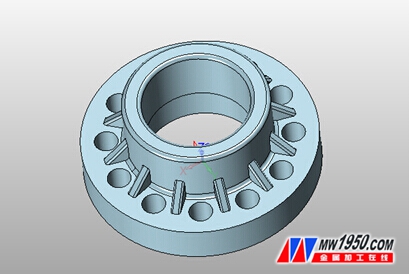
Figure / flange model
So how do we get through the modeling process? Based on Zhongwang 3D, the author summarizes the idea of ​​modeling as follows: When modeling the part, you can use the extended boss feature to construct two cylinder assemblies. Since the circular holes and the ribs on the surface of the flange are evenly distributed around the central axis of the part, it is only necessary to create a circular hole and a rib, and then use the circumferential array feature to copy other holes and ribs without having to Build separately. Finally, the rounding transition is generated and the entire modeling is completed.
Below we will break down its specific modeling steps as follows:
The first step: build a cylindrical assembly
(1) New parts.
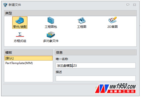
Figure 1 / Part Creation Interface
(2) Select the xy plane to insert the sketch and start sketching (marked as sketch 1).
(3) Click "Circle" to draw two circles with the origin as the center and the radius of 120mm and 60mm respectively. as shown in picture 2.
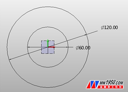
Figure 2 / Sketch
(4) Click the "stretch" function and set the parameters (Fig. 3) to obtain the cylinder 1, as shown in Fig. 4.
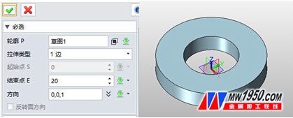
Figure 3 / Stretch setting window Figure 4 After stretching
(5) Click the "Insert Sketch" option and select the outer section on the cylinder to obtain the sketch 2, as shown in Figures 5 and 6.
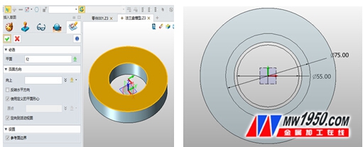
Figure 5 / Insert Sketch Figure 6 / Sketch 2
(6) On the basis of Sketch 2, draw a circle with the coordinates origin as the center and diameters of 75mm and 55mm respectively, and then click "stretch" to get the cylinder 2.
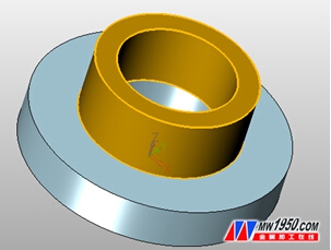
Figure 7 / After stretching the cylinder 2
Step 2: Generate a uniform circular hole
(1) Click "Insert Sketch" to get the sketch 3, and the plane selects the upper plane of the cylinder 1.
(2) Draw a point 47 mm from the axis of the cylinder, as shown in Figures 8 and 9.
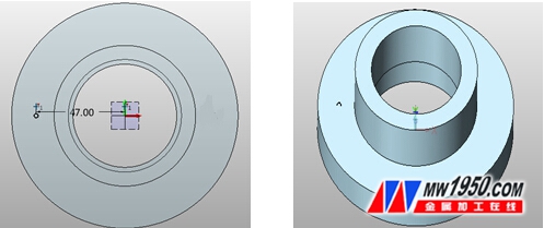
Figure 8 / New Sketch 3 Figure 9 / Finishing Point Drawing
(3) Click the "hole" option, according to the construction of the parts in this case, select the position of the point, according to Figure 10, set the relevant parameters, draw a hole with a diameter of 12mm, the effect is shown in Figure 11.
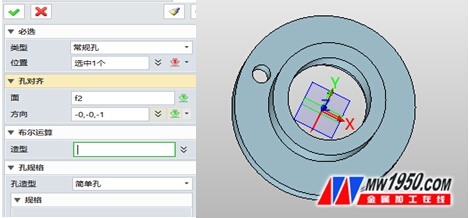
Figure 10 Figure 11
(4) Click the "array" option to select the round type column. For related parameter settings, refer to Figure 12. After the setting is completed, the result of Figure 13 will be obtained.
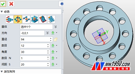
Figure 12 Figure 13
(5) Click "Insert Sketch" to draw sketch 4 in xz plane, as shown in Figure 14.
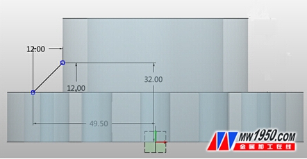
Drawing of Figure 14/Sketch 4
(6) Click the "Move" option and select the line drawn in Sketch 4 to rotate in the direction. The direction is the z-axis direction and the angle is 15 degrees. As shown in Figure 15.
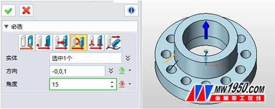
Figure 15 / Rotation effect diagram
(7) Click the "rib" option, the relevant parameter settings refer to Figure 16, the thickness of the rib is 5mm, and the effect of Figure 17 will be obtained after the setting is completed.
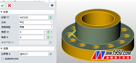
Figure 16
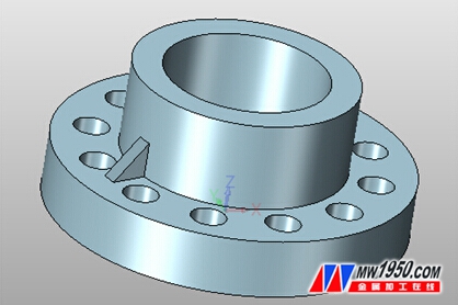
Figure 17
(8) Click on "Array". The related parameter setting reference is shown in Figure 18. This step is similar to the above array operation on the holes.
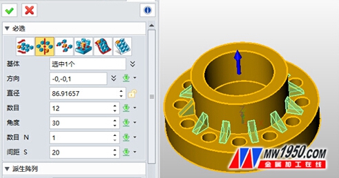
Figure 18
(9) Click on the "rounded corner" to create a fillet feature for the flange. The rounded corner of the cylinder is 2mm, and the rounded corner of the rib is 1mm, as shown in Figure 19.
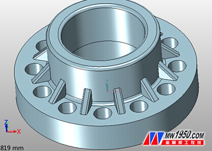
Figure 19
After the above two steps, the 3D CAD/CAM software can be used to model the flange parts.
Through the operation of this modeling, I believe that we can better grasp how to use the 3D stretching, circular array, adding ribs, rounding and other feature operations to construct a 3D solid model.
More Zhongwang 3D tutorial, please click
3D design software in the hope 3d free download
Smart Faucet,Smart Faucet Price,Smart Faucet Product
Yuyao Zelin Sanitary Ware Co., Ltd , https://www.zelinsinkfaucet.com